Hints for techs using the old Dick Smith ESR meter
A lot of this
info also
applies to the current Blue ESR meter from Anatek
Click
here if your newly-built meter's not working properly.
Click
here
if you don't have a variable DC power supply to set up VR1.

New ESR meter users and the front panel chart...
People regularly ask me for more specific ESR figures and for
figures relating to caps not shown on the front panel chart.
The chart is really only
meant to be a rough guide to
what to expect until you get used to ESR measurements you'll encounter
in repair situations, and here's part of an e-mail I recently sent in
reply to these questions, which I hope explains this a bit more clearly:
Once you've been using the meter
for a while and get
used to the kinds of readings you get from electrolytic caps, you'll
see that there's quite a large amount of variability in the figures
you'll get. ESR varies between manufacturers and different capacitor
types, such as normal and high temperature-rated caps. ESR also varies
with ambient temperature. What this means is that if you encounter a
cap not shown on the front panel chart, all you really need to do is
mentally go for the average of the figures of the caps which are shown
on either side of it.
I expect this is giving you the
feeling that it's going
to be impossible to know whether the cap you're checking is good or
not. In fact in my own experience and that of lots of techs I've heard
from, when a cap's ESR is high enough to cause a problem, it will
generally measure at least 10 times the value on
the chart, and more commonly 30+ times the chart value
or give no reading at all. Sick electrolytic caps usually stand out
really clearly.
I don't have a lot more ESR
information, but if you want
to find data sheets on specific electrolytic caps, Doug Jones has a
page of links on his Capacitor
Wizard website which should be helpful to you [Thanks,
Doug!!]. I hope this has better explained the situation with
ESR figures....
Caution... not all
electrolytic caps fail due to high ESR or leakage.
Kevin of Kevin's TV Repair gave this important warning:
"Your
ESR meter sometimes misses caps that show a good ESR reading, but have
a capacitance value of half or less of what they should be. This has
only happened twice, but I rely so heavily on your ESR meter that I
drove myself crazy trying to find the problem elsewhere! Now I know if
everything checks out OK, to pull the caps out of circuit and measure
their value."
I've heard of this happening maybe
3 times to other
techs, so please keep it in mind if nothing seems to make sense, that
the ESR meter might be getting fooled by one of these very unusual
caps.
Now here's the current list of hints. If you
have any handy suggestions I can put on this page, please E-MAIL ME
(1) The way to hold the 9V alkaline battery in place (in the Mk1
meter) is to lay it in the bottom of the case and place a
suitable-sized piece of thick foam plastic over it. Then the circuit
board will hold it snugly in place when the front panel is screwed
down. Dick Smith Electronics now includes a piece of foam in the kits
for this purpose.
Alternately, Andy
in Perth West Australia said:
"Use double sided tape (as I have) to secure the battery. Place 2
strips of tape on the battery on adjacent sides, then press into place
against the bottom and one side of the box. A semi permanent fix, which
allows fairly easy removal, but no major modifications."
Or as Deane McIntyre
suggested: "I found that the
small cardboard boxes that pilot lights come in (boxes of ten 47's for
example) are the exact size to contain the battery and to fit snuggly
into the enclosure under the board."
(2) The "Approximate worst ESR
values" table on the
front of the meter were taken from a fairly old capacitor catalog, and
capacitor technology has evolved a bit since then. For example, many
105║C electrolytics have an ESR up to nearly double those values even
when brand new, and other electrolytics have a lower ESR even when old.
From my experience if an electrolytic has an ESR more than double the
table value for its capacitance and voltage rating, it's wise to check
it against a new one and/or replace it to remove the chance of it
causing problems in the future.
The best way to be
confident about whether a suspect
capacitor is good or not is to measure the ESR of one or more brand-new
ones of the same value and working voltage!
(3) Hank Sievers
said, "Bob
Parker's meter can also be used as a go-no go type. I have found that I
can consider everything below 3 ohms as good, and all over 10 as bad,
with very few falling in the doubtful category'. I agree that except
for very large and very small caps, this is a useful 'rule of thumb'".
Thanks, Hank!
(4) The "DISCHARGE CAPACITOR
BEFORE MEASURING!" warning on the meter front panel is a little
over-cautious.... "Test only discharged capacitors!"
would have been better. Nearly all electrolytics are discharged by
their surrounding circuitry within a few seconds of the power being
disconnected, so you can generally poke around with the meter without
worrying about this. The only caps which are likely to need deliberate
discharging are the main filters in amplifiers and other large power
supplies.
(5) Glenn Watkins
has pointed out that a shorted
or partially shorted cap can check OK (ie: low resistance), so if you
check a cap and the indicated ESR seems too good (low) to be true, it's
wise to check it out with an ohm meter. Or you can parallel the ESR
meter and an ohm meter and look for shorts at the same time... see #13
below.
(6) Glenn also
said, "It's very hard to press the
test lead tips together to get a steady reading before pressing the
button to zero the display. I found that if the test leads have sharp
tips, you can press them both on a solder pad (on a PC board) and the
leads will penetrate the solder a little giving a good solid reading".
Thanks Glenn!
(7) David aka
'Starwriter' provided this
alternative way of shorting the test leads: "To zero the meter, I poke
the probe tips into 1 of the philips screws on the front of the case.
It's easy to hold the leads together this way while you push the
button." Good idea and thank you kindly, David!
(8) The meter puts out regular
bursts of 10us pulses at
a 2KHz rate, at an open-circuit amplitude of about 600mV P-P. At a
pinch you can use it as an audio signal source to check speakers,
amplifiers etc. The pulses have a fast rise/fall time, so it would
probably make a crude RF signal injector as well. Thanks to 'Kiwi'
Joe Lussy for suggesting this!
(9) Varying contact resistance
between the banana plugs
and sockets can cause unsteady readings, but if you give each plug a
big squirt of CRC "CO Contact Cleaner" then rapidly jiggle it in its
socket for a few seconds, this reduces the problem considerably. Also
be aware that the nuts holding the banana sockets can work
themselves loose
over time, causing a variable and gradually increasing indicated test
lead resistance... this happened on my own prototype meter and others
I've heard about.
(10) If you'd like to get more
battery life out the
meter (and are feeling a bit adventurous), you can replace IC1 (78L05)
with an LP2950CZ-5.0 and replace R25 (47k) with 27k.
Then adjust VR1 so the low battery warning triggers at 5.6V
instead of the original 7.0V. Thanks to G. Freeman
in South Australia for this idea which was published in the August '98
issue of Electronics Australia magazine.
Note: When using the MK2
ESR meter's self-test function after doing this modification, it will
need to be powered from 6.2 - 6.8V, not 9V as it
originally was.
(11) Mark Stevenson
has devised some ingenious methods of installing a 'Low Ohms'
buzzer in the ESR meter, which make it less necessary to
watch the displays while you're using it. Click here
to get his instructions on how to do it, as a text file. And click
here for the schematic. Thanks for that, Mark!
(12) I haven't tried it myself,
but I've heard from
several sources that the ESR meter is quite good at indicating the
condition of batteries of both the normal and rechargeable kind. Click
here to visit the John's Jukes website where John
Robertson has some information about this.
(13) John Robertson
also made this handy
suggestion which should work OK: "I thought you might want to modify
your ESR meter hints page to have folks try out my use of the ESR meter
and a regular Ohm-meter in parallel to find those pesky shorted caps. I
found that the cheap shop digital meter worked just fine and using its
low ohm beeper function finds the shorts!". Thanks again, John!
 (14) Col Hardy
said: "Love the meter, but had a few quirks with the banana sockets
provided. I soldered a twin cable to the the PCB terminals and ran it
out of one of the sockets, soldered sewing pins to the wires, works
great. To increase battery life 20 fold, cut the track from the display
mplex emitters (Q12/13) and add a resistor in series. I used a 500 ohm,
so a 470 or 390 would be good starting points. Battery life is extended
from a few weeks to 6 months or so (though the displays are dimmer)."
Col's extra resistor
is in the top left corner of his meter
board here.
Thanks, Col!
(14) Col Hardy
said: "Love the meter, but had a few quirks with the banana sockets
provided. I soldered a twin cable to the the PCB terminals and ran it
out of one of the sockets, soldered sewing pins to the wires, works
great. To increase battery life 20 fold, cut the track from the display
mplex emitters (Q12/13) and add a resistor in series. I used a 500 ohm,
so a 470 or 390 would be good starting points. Battery life is extended
from a few weeks to 6 months or so (though the displays are dimmer)."
Col's extra resistor
is in the top left corner of his meter
board here.
Thanks, Col!
(15) Mike (Moby) Diack
made this useful
suggestion: "Haven't needed to test a single cap yet, but (being a
fixer of big PA amps) it's just fine for 1/ Finding a punched through
transistor in a big parallel bank and 2/ Finding a crook bypass cap
amongst dozens between +5 and gnd." I hadn't thought of that, so thanks
Mike!
(16) If you're swapping between
powering the meter from
a battery and an external 9V DC power supply, there's a little
modification you can do which disables the meter's automatic switch-off
function when running from the power supply. Click here
for the circuit as a .gif file. The extra NPN transistor can be any
small-signal one, such as BC548 etc. Dave Burla
assures me that it does work!
(17) ESR meter
carry case! Tom Chipman
recommended: "I purchased a case at Walmart for $8.88. Look in the
Women's purse section. It is actually some type of makeup case,
configured in the form of a miniature footlocker, but without a tray,
just a rectangular box with a lining. It is just the right size to
accomodate the meter, with enough room to tuck the leads along side.
Because it is rigid, there is no danger of transferring the on/off/zero
switch, when the case is closed, or handling it." Thanks Tom, it sounds
like a great idea!!

(18) Stop the push button from being bumped in your
toolbox...
Ricky Lee Ponder sent this idea and excellent photo
to
illustrate it: "I have a little tip for people who might want to carry
this in a toolbox or bag. I got concerned that something would always
be pushing the button. So I took a plastic housing off of a D.C. barrel
plug and it slides right down over the red button and threads onto the
switch threads. This prevents anything from pushing the button until
you take it off. I did have to leave the lock washer off so enough
threads remained for the cover to thread on to."
- Or you could try -
Mark Twitchell [N2WAE] had this similar thought:
"Something I
was going to try with the ESR meter is to put a washed out cap (note- I
mean a CAP, as in bottle cap, not capacitor) from a spent tube of lip
balm (Chapstik, Blistex, etc.) on the power switch button. Make sure
that the cap is plastic, NOT metal. You can try and cut or punch a
clean hole in the center of the bottom to pass the power switch
threaded shaft, and then screw down the nut using long nose pliers, to
protect the switch from being pushed accidentally in your pocket or
tool kit (may keep the battery fresh longer). If the cap is too tall,
try putting it back on the original container, and cutting it around
with a razor knife at the lower height and re-fit it."
- Or this -
Bob Ecclestone did it
this simple way: "I also
had problems with the first unit switching on in the toolbag and I
glued a tube cap over the switch, but this caught on other things in
the bag. So on the second unit, I cut the button off the switch stem
and filed the stem down so it was just below the switch body when
pushed in. Now the switch does not turn the unit on if inadvertently
bumped in the bag, but it is still quite easy to turn it on."
Thanks, guys!
 (19)
From Iain Emerson:
"Like Col Hardy I too had a problem with the test leads on loose caps.
Fixing a small piece of PCB (two pads) just above the display and
connecting them to the terminals through the casing allowed the leads
of a cap to be placed directly on the pads and tested, and it's also a
quick way to zero the meter with just one hand free."
(19)
From Iain Emerson:
"Like Col Hardy I too had a problem with the test leads on loose caps.
Fixing a small piece of PCB (two pads) just above the display and
connecting them to the terminals through the casing allowed the leads
of a cap to be placed directly on the pads and tested, and it's also a
quick way to zero the meter with just one hand free."
The pad measures 40mm x 8mm with a 3mm gap
(copper
removed with a craft knife) half way along. The pad sits on a 5mm thick
piece of foam rubber held in place by two-sided sticky tape. Two 2mm
holes were then drilled in the front panel for the leads that are
soldered to the two test lead sockets and pads respectively ie; left
pad, left socket etc.... Thanks Iain!
(20) Alastair MacGregor has found that the ESR
meter can identify suspect inductors... "If an inductor has shorted
turns it loses inductance but may maintain resistance. So if I have a
line drive transformer for example, I can stick the ESR meter across
it. If get a reading, the transformer has shorted turns or should be
investigated more."
Choong Keat Yian
added that he tests small
transformers such as TV deflection and SMPS power supply ones by first
measuring their DC resistance with his Fluke 12 DMM. If he sees a very
low resistance (maybe 0.3 ohms), next he connects the ESR meter to it.
If the ESR meter doesn't show "- " (more than 99
ohms), it
almost certainly means that the inductor has shorted turns. He said,
"Best of all, all this can be done while onboard without desoldering in
most cases".
(21) 'DICK SMITH' TIP by Joe Sopko, writing for "THE
SPEAKER", the newsletter of NesdaOhio.
 "After
a couple years of use, I just had
the first
failure of my prized 'Dick Smith' ESR Meter. Other owners know that
when you use the meter, the first press of the push button switch turns
it on, then you put the probes together & the second press of
the
switch subtracts the resistance of the meter leads from the display
& 'zeros' the meter. Well, my failure was that the second press
turned it off - instead of zeroing the display. Bummer! How can you use
a meter that turns itself off when you go to use it? That makes it just
as bad as an employee! At least MY employees tend to turn themselves
off when I go to use them. The cure was simple - if you know it. I wish
I would have known this before I disassembled the meter &
looked
for a problem that wasn't internal. Over the years, the probes had
slowly built up a slight coating of oxidation. They still looked bright
& shiny, but in fact when I put them together, they were
reading
about 2.1 ohms. That was enough to tell the meter that the probes were
NOT together and to shut off the meter on the second press. The cure? A
quick wipe of the probes & jacks with tuner cleaner. Problem
solved! It made me so happy I just had to grab a SMPS & measure
some caps." Thank you, Joe!
"After
a couple years of use, I just had
the first
failure of my prized 'Dick Smith' ESR Meter. Other owners know that
when you use the meter, the first press of the push button switch turns
it on, then you put the probes together & the second press of
the
switch subtracts the resistance of the meter leads from the display
& 'zeros' the meter. Well, my failure was that the second press
turned it off - instead of zeroing the display. Bummer! How can you use
a meter that turns itself off when you go to use it? That makes it just
as bad as an employee! At least MY employees tend to turn themselves
off when I go to use them. The cure was simple - if you know it. I wish
I would have known this before I disassembled the meter &
looked
for a problem that wasn't internal. Over the years, the probes had
slowly built up a slight coating of oxidation. They still looked bright
& shiny, but in fact when I put them together, they were
reading
about 2.1 ohms. That was enough to tell the meter that the probes were
NOT together and to shut off the meter on the second press. The cure? A
quick wipe of the probes & jacks with tuner cleaner. Problem
solved! It made me so happy I just had to grab a SMPS & measure
some caps." Thank you, Joe!
(22) Brian Gerber C.E.T. said: "Most techs know
they can sometimes find a faulty cap with a can of freeze spray. If you
have a cap that the ESR is say marginal, it still may not perform under
a load condition until it warms up. I have found if you have this
condition and you freeze all the caps and recheck with the ESR meter,
they stick out like a sore thumb!!!" Good idea, Brian. :-)
(23) Tony Marsillo (Nutmeg Repair) gave us this
useful advice: "For measuring caps in circuit using one hand I
purchased a set of Tweezer
Probes from MCM electronics, part number 76-001.
The tips are such that they can be shorted together to zero the meter.
Don't get the Pomona type, their tips do not touch when squeezed
together. I have been using the meter for about 2 years and it has
saved me quite a lot of time. Thanks."
Thank you too, Tony!
However, as Richard Sato suggested, if you're
good at using chopsticks then you don't really need tweezer probes.
Just hold the normal probes in the same way. It's surprisingly easy
once you get used to it. I've been doing this for years.
(24) Peter Morgan found yet another use for the
meter: "Had occasion to have to trace out the schematic of a board
which had numerous tracks/vias under the chips - a real PITA.
Eventually (an hour or more) I had a hand-drawn schematic. Now to
verify ... I remembered that the ESR meter pulses are below the
threshold of diode junction conduction, so I proceeded to use it as a
yes/no check of every pin to every other. Must have been all of five
minutes and all permutations had been tested. I'm probably not the
first to use it in this way, but it is another use for this great
device."
Maybe not the first,
but the first I've been told about.
Thanks for sharing your idea with everyone, Peter. :-)
(25) John Robertson at John's Jukes noticed an
old article about problems caused by poor grounding in tube guitar
amplifiers and commented that the ESR meter is very good at locating
bad connections. So there's another use for it. :-)
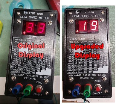
Upgrade your displays!
LED
display technology has improved a lot in the decades since the Dick
Smith ESR meters came out.
Kiel Lydestad said, "I replaced the displays with a pair of Lite-On LSHD-5503 red 17mcd modules.
What a difference!" and sent me this photo to prove it...
Extra protection diodes
Quite a lot of people are installing a pair of 1N5404 or similar high
current diodes in inverse parallel across the test lead jacks/sockets,
to give more protection if the meter's connected to a large charged
capacitor. So far I haven't heard of any meters being damaged after
this modification, though it's not good for the test lead probes, the
diodes or the capacitor.


Remember that you cannot test the ESR of batteries
after installing these diodes!
Stan Labinsky Jr
provided these nice photos of his installation, which is the best
& neatest I've seen. Thanks again Stan!

Jacques Carrier's "new" ESR meter.
---------------------------------
Upon reading your article about the new version of your ESR meter I finally decided to
tune-up my ESR meter.
After using it for about 3 years, it was time to finally remove a few annoyances:
1) I desoldered R25 to disable the 2 min. auto shut-off function. Great! No more powering up to do.
Time saver too.
2) I also installed 2 diodes (1N5404) across the inputs. It is so tight inside the meter......... no problem-----Ł I simply
put them outside........ (They are mounted on a stackable banana plug in which the output leads are inserted.) It does
not look too bad and you do not have to open the case if you have to replace them. Great protection for this priceless
meter!
3) I removed the battery (power hungry meter)!!! Expensive 9V Duracell battery eliminated.
I installed a small 9VDC adapter (13 VDC unloaded) followed by an in-line 7808 regulator (mounted inside a plastic fuse
box).
I left the battery connector inside (properly insulated) just in case I ever need to use the battery again.
The adapter is connected to the meter through a small polarized male/female connector.
The ESR meter is now much user friendly (....for me). I am madly in love with my "new" meter!!!!
Graphs... Graphs... Graphs...!!
Matt Warren has created some graphs of typical new capacitor
value vs working voltage vs ESR
which are interesting in their own right and also great for working out
values in between those in the meter's front-panel chart. Just click on
the following links to get them:
Graph
#1
Graph
#2
Graph
#3
And if you own another ESR meter such as Doug Jones' highly respected Capacitor
Wizard
and would like a copy of the chart of approximate worst-case ESR
figures from the front of my meter for reference, CLICK HERE
to download one as a text file, or HERE as a .pdf
file you can print out!
Thanks to M Davis
for suggesting I make this
available!
And now the answer to the question 'everyone' is asking... Why
does the original "Mark 1" meter flash 'EA' at switch-on? Answer:
'EA' stands for 'Electronics Australia',
the magazine this meter appeared in as a construction project, back in
January 1996. Sadly this magazine no longer exists. The "Mark 2" and Blue ESR meters don't do this.
Finally a big 'THANK YOU' to all you techs who've bought this
meter
kit and said good things about (and constructively criticised) it, both
on the sci.electronics.repair newsgroup and to me directly. I really
appreciate it!
Back to the ESR meter
page...
Back
to the home page...
Last update: 21 July, 2024